xArm Controller RS-485 (Modbus RTU) User Guide
1. Overview
This manual describes the RS-485 communication capabilities of the UFACTORY xArm controller and how to use them under the Modbus RTU protocol.
The controller currently supports:
- Modbus RTU Master
- Modbus RTU Slave (Controller AC1320 or later, AC8520 or later, firmware V2.7.104 or later)
2. Modbus RTU Master
In Master mode, xArm actively communicates with external RS-485 slave devices.
2.1 Interface Definition
| Terminal | Description | Note |
|---|---|---|
| M_A | RS-485 A / D+ | Master |
| M_B | RS-485 B / D- | Master |
| GND | Signal Ground |
2.2 Communication Parameters
| Parameter | Default | Range |
|---|---|---|
| Baud Rate | 2000000 | 4800, 9600, 19200, 38400, 57600, 115200, 230400, 460800, 921600, 1000000, 1500000, 2000000, 2500000 |
| Data Bits | 8 | |
| Stop Bits | 1 | 1, 2 |
| Parity | None | None (N), Odd (O), Even (E) |
| Timeout | 50 ms | 1–9999 ms |
2.3 Control Methods
2.3.1 UFACTORY Studio
RS-485 Port: Control Box Protocol: Modbus RTU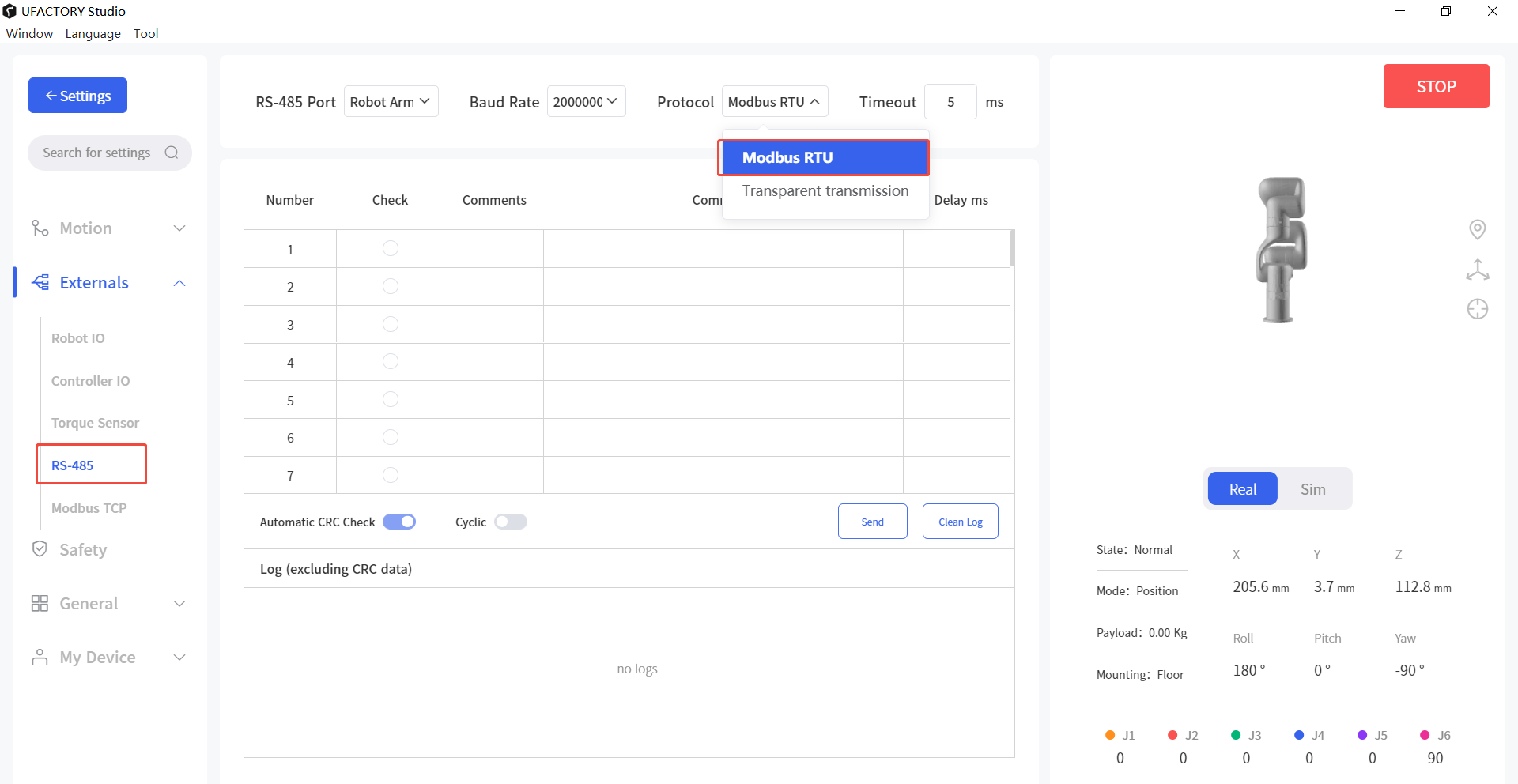 CRC will be appended automatically after the input command.
2.3.2 Python SDK
- Set controller baud rate
python
arm.set_rs485_baudrate(200000, target='control_box')- Set timeout
python
arm.set_rs485_timeout(1000, target='control_box')- Send data
python
arm.set_rs485_data([0x08, 0x06, 0x01, 0x00, 0x00, 0x01], target='control_box')3. Modbus RTU Slave
In Slave mode, xArm can be accessed by a PLC or host computer.
3.1 Interface Definition
| Terminal | Description | Note |
|---|---|---|
| L_A | RS-485 A / D+ | Slave |
| L_B | RS-485 B / D- | Slave |
| GND | Signal Ground |
3.2 Communication Parameters
| Parameter | Default | Range |
|---|---|---|
| Slave ID | 1 | 1–247 |
| Baud Rate | 9600 | 4800, 9600, 19200, 38400, 57600, 115200, 230400, 460800, 921600, 1000000, 1500000, 2000000; (0-12) |
| Data Bits | 8 | |
| Stop Bits | 1 | 1, 2 |
| Parity | None | None (N), Odd (O), Even (E); (0-2) |
3.3 Parameter Configuration
Set parameters:
python
arm.set_modbusrtu_params(slave_id=1, baudrate=9600, stopbits=1, parity=0)Get parameters:
python
arm.get_modbusrtu_params()Example output:
text
(0, [1, 9600, 1, 0])3.4 Register Mapping Examples
3.4.1 Function Code
- Discrete input register
- 0x02: Read multiple discrete input registers
- Input register
- 0x04: Read multiple input registers
- Coil register
- 0x01: Read multiple coil registers
- 0x05: Write single coil register
- 0x0F: Write multiple coil registers
- Holding register
- 0x03: Read multiple holding registers
- 0x06: Write single holding register
- 0x10: Write multiple holding registers
- 0x16: Mask write single holding register
- 0x17: Read and Write multiple holding registers
3.4.2 Status Registers (Read Only)
Discrete Input Registers (1 bit, READ only)
| Address (Dec) | Address (Hex) | Description |
|---|---|---|
| 0–31 | 0x00–0x1F | Controller digital input IO (16 valid) |
| 32–39 | 0x20–0x27 | Tool digital input IO (2 valid) |
| 40–127 | 0x28–0x7F | Reserved |
Input Registers (16 bit, READ only)
| Address(Dec) | Address(Hex) | Description |
|---|---|---|
| 0 ~ 1 | 0x00 ~ 0x01 | 32 controller Digital Inputs (Now only 16 effective) |
| 2 | 0x02 | 8 tool Digital Inputs (Now only 2 effective) |
| 3 ~ 6 | 0x03 ~ 0x06 | 4 controller analog inputs (now only 2 effective), it is 1000 times the real value |
| 7 ~ 10 | 0x07 ~ 0x0A | 4 tool analog inputs (now only 2 effective), it is 1000 times the real value |
| 11 ~ 31 | 0x0B ~ 0x1F | Reserved |
| 32 | 0x20 | Robot Error code |
| 33 | 0x21 | Robot Warning code |
| 34 ~ 35 | 0x22 ~ 0x23 | Counter value (0x22 stores the higher 16-bit, 0x23 stores the lower 16-bit) |
| 36 ~ 63 | 0x23 ~ 0x3F | Reserved |
| 64 ~ 72 | 0x40 ~ 0x48 | Current TCP coordinate of x/y/z/roll/pitch/yaw/rx/ry/rz values, register values are 10 times the real numbers (unit: mm, degree) |
| 73 ~ 76 | 0x49 ~ 0x4C | TCP payload mass(1000x)/center_x(10x)/center_y(10x)/center_z(10x) (unit: kg, mm) |
| 77 ~ 82 | 0x4D ~ 0x52 | TCP Offset, register values are 10 times the real numbers(unit: mm, degree) |
| 83 ~ 88 | 0x53 ~ 0x58 | User/world coordinate offset, register values are 10 times the real numbers(unit: mm, degree) |
| 89 ~ 95 | 0x59 ~ 0x5F | joint (J1-J7) angles, register values are 10 times the real numbers(unit: degree) |
| 86 ~ 102 | 0x60 ~ 0x66 | joint (J1-J7) temperature (unit: degree Celsius) |
| 103 ~ 109 | 0x67 ~ 0x6D | joint (J1-J7) speed, register values are 10 times the real numbers(unit: degree/s) |
| 110 | 0x6E | Robot TCP linear speed, register values are 10 times the real numbers(unit: mm/s) |
| 111 ~ 127 | 0x6F ~ 0x7F | Reserved |
3.4.3 Control Registers (Read / Write)
Coil Registers (1 bit, READ/WRITE)
| Address(Dec) | Address(Hex) | Description |
|---|---|---|
| 0 ~ 31 | 0x00 ~ 0x1F | 32 controller Digital Output (Now only 16 effective) |
| 32 ~ 39 | 0x20 ~ 0x27 | 8 tool Digital Output (Now only 2 effective) |
| 40 ~ 127 | 0x28 ~ 0x7F | Reserved |
| 128 ~ 134 | 0x80 ~ 0x86 | joint (J1-J7) brake states |
| 135 ~ 141 | 0x87 ~ 0x8D | joint (J1-J7) enable states |
| 142 | 0x8E | Reduced mode (0: OFF, 1: ON) |
| 143 | 0x8F | Digital Fence (0: OFF, 1: ON) |
| 144 | 0x90 | isPaused (0: False, 1: True) |
| 145 | 0x91 | isStopped (0: False, 1: True) |
| 146 ~ 159 | 0x92 ~ 0x9F | Robot Mode (14 bits for mode 0-13 respectively, 0: not in this mode, 1: in this mode) |
| 160 ~ 255 | 0xA0 ~ 0xFF | Reserved |
| 256 ~ 511 | 0x100 ~ 0x1FF | General purpose, user defined |
Holding Registers (16 bit, READ/WRITE)
| Address (Dec) | Address (Hex) | Description |
|---|---|---|
| 0-1 | 0x00-0x01 | 32 controller Digital Outputs (Now only 16 effective), each bit correspond to one IO in order |
| 2 | 0x02 | 8 tool Digital Outputs (Now only 2 effective), each bit correspond to one IO in order |
| 3-6 | 0x03-0x06 | 4 controller analog outputs (now only 2 effective), it is 1000 times the real value |
| 7-10 | 0x07-0x0A | 4 tool analog outputs (currently NOT EFFECTIVE), it is 1000 times the real value |
| 11 | 0x0B | Modbus RTU slave ID |
| 12 | 0x0C | Modbus RTU slave baud rate |
| 13 | 0x0D | Modbus RTU slave stop bit |
| 14 | 0x0E | Modbus RTU slave parity |
| 15-31 | 0x0F-0x1F | Reserved |
| 32 | 0x20 | Robot Mode |
| 33 | 0x21 | Robot State |
| 34-47 | 0x22-0x2F | Reserved |
| 48-63 | 0x30-0x3F | Offline (Blockly) Task (only effective by writing multiple (max 16) holding registers to address 0x30 via function code 0x10, each register value correspond to one Blockly project with specific naming convention, for example: value 1 for project '00001', 12 for project '00012', projects will be executed automatically in order) |
| 64 | 0x40 | Gcode(Firmware≥2.4.0), trigged the gcode file under modbus_tcp folder. |
| 65-255 | 0x41-0xFF | Reserved |
| 256-511 | 0x100-0x1FF | General purpose, user defined |